Yatch Club

Introduction:
Yatch club project was a luxury Island development project in the middle east. The scope of work done on this project included the concept design and the schematic design stage. The Building had the features of Naval Arcihtectue and the concept was designed by a famous Yatch designer. I was responsible to develop the structural design scheme from the concept for the project.
Roof Design problem:
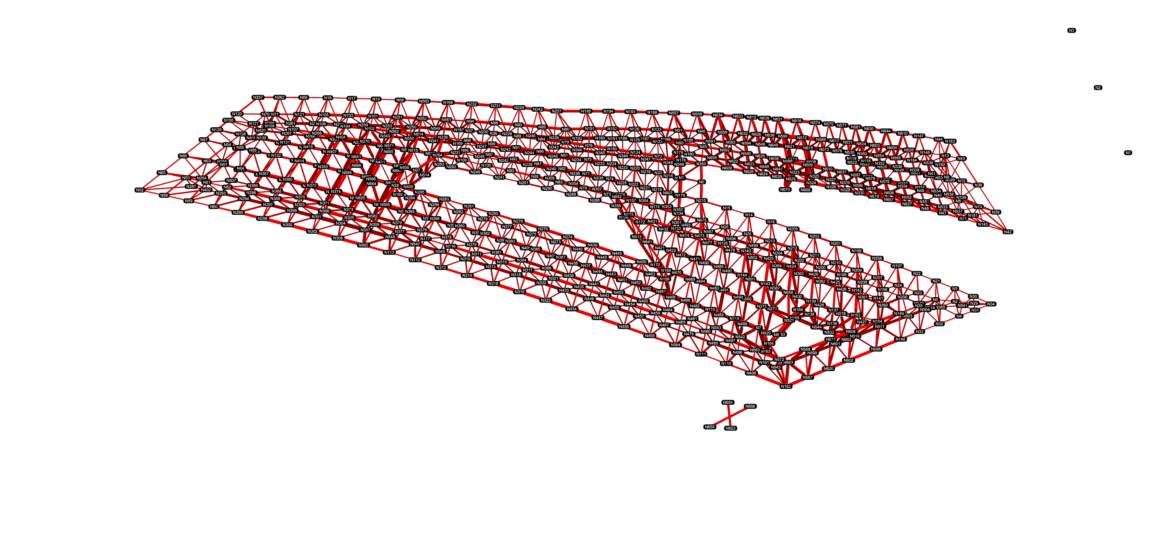
The biggest challenge in the whole project was the design of the roof which resembeled the form of a bird or an aeroplane. The roof covered a terrace gathering space and had long spans over 20- 25 meters with limited locations available for the supports.There was a strict restriction on the height of the roof as well considering the architectural intent. Considering the constraints and the requirements the design brief was to develop a structural solution for the roof which had the least ammount of material with rationalised geometry for constructability and which would come closest to the architectural intent provided by the concept designer Roof design approach Several approaches were tested for the roof design in the Yatch club. A beam/truss solution and a space frame solution was tested and the beam solution was discarded due to the overwhelming performance of the space frame solution for the weight of steel.The design being deflection driven it was quite a challenge to come up with a light weight solution for the problem.
Geometry Rationalisation:
The form of the roof was very close to a perfect cylinder >5% deviation from the best fit cylinder. So the roof outline and boundary was projected on a best fit cylinder which was used as a base for the design. See Images 1-5 for the whole process involved in the best fit approach. The geometry of the space frame itself was a combination of radial and rectangular grid which offered the best value in terms of keeping the sizes of the steel sections uniform. The resulting iteration of the design had almost 34% of the roof members with the same length. Structural design The structural design for the scheme was initially performed in the Rhino + Grasshopper enviornment using the FEA plugin Karamba and then the results were checked in CSI SAP for the validity of the design.
- A Parametric script capable of changing the grid size and performing the rationalization process as explained in the previous section was setup. The resulting geometry was converted to a Karamba model where a suite of Circular hollow sections was selected after consulting the local contractor for the list of commonly available sections in the region.
- A evolutionary multi-objective optimization was setup which minimized the mass of steel and unique members within the deflection servicability limits of the roof structure.
Constructability checks:
Another big constriant in the roof design was the ease of construction aspects involved. The two main criteira in this was to avoid the welding of joints as much as possible and to check the angle between the Circular hollow sections choosen for the roof design. A ball and socket type of connection was choosen for the space frame solution and a parametric scipt was developed which did the following things.
- Built a graph network of the complete roof structure consisting of ball joint nodes (vertices) and the circular hollow section memebrs as ( edges )
- Pull the right section size from the structural analysis in SAP for all memebers and connections
- Check if there are any clashes between the memebers or at node junction and check the workability of the angle of connection at the site
Further more an optimization was run to mimize the welded joints and the reslting roof had only 6 welded joints